Friday, December 10, 2010
Dec. 10 Log
Today Mr. Cuttrel showed the electrical engineers the wire disconnects that are here at the school. Next class we will be experimenting and rummaging through last year's ROV remnants. I spoke with my partner RB about how we are going to tackle the building in the next few weeks.
Wednesday, December 8, 2010
Dec. 16 Log
On December 13th and 15th the rest of the Electrical Engineers and myself did some experimental work in the Systems Lab. We went through the remnants of last years ROV and discovered many reusable items including motors, cameras, and wire. The motors are either Attwood 3000 motors and a series of converted bilge pumps. All but 2 of the Motors work and all of the bilge pumps are functional. We tested them with a 9V battery.
Friday, December 3, 2010
Dec. 3rd Log
Asked questions about future homework assignment and formats of lists in developmental work.
Wednesday, December 1, 2010
Dec. 1st. Log
Today I am researching which wires will be best to use for the tether and the best wire connectors. Essentially I am working out the kinks of my parts list and plan of procedures list.
Wednesday, November 24, 2010
Nov. 24 Log
Research to find which wire will be used. Find a picture of the disconnects. Tie up loose ends to Developmental Work.
Friday, November 19, 2010
Marking Period II Log
Friday 19 November 2010: Today I am refining my CAD drawings and finishing all developmental work such as writing the captions that go along with pictures. I should add more imagery to my blog overall.
I completed my Calender due dates.
I completed my Calender due dates.
Wednesday, October 20, 2010
Rationale
Rationale:
Alternate Solution 1:
Alternate solution 1 a three motor configuration with two of the motors side by side facing the rear located in the rear and the third vertical motor placed centrally to the ROV facing propeller up. Solution 1 allows for simple controls, powering the right motor turns the ROV left and vice versa, powering both motors forward at the same time will move the ROV forwards, and powering the vertical motor will move the ROV in the water column.
Alternate Solution 2:
Alternate Solution 2 is a four motor configuration where all four motors are located in the rear of the ROV, thus allowing for fine maneuvering while operating the ROV. This configuration presents an issue for balancing the weight of the ROV.
Alternate Solution 3:
Alternate solution 3 is made of six motors each on opposing faces of each other. There is a motor for up, down, a left plane, right plane, forward, and backwards and each is independent of each other.
Alternate Solution 4:
Alternate Solution 3 is has three motors, one to propel the ROV and two to control steer the ROV. The two sets of flaps redirect the water flow over the ROV and make the ROV either turn left, right, up, and down.
Design: |  |  |  |  |
| Circuit difficulty | 3 | 3 | 2 | 3 |
Movement forward and backward | 3 | 4 | 1 | 4 |
Movement left and right | 2 | 3 | 3 | 1 |
Movement up and down | 3 | 3 | 2 | 1 |
| Operational in all planes | 1 | 4 | 3 | 2 |
Total | 12 | 17 | 11 | 11 |
Design One scored 12 out 20. Wiring this circuit consists of three double pole double throw switches which is basic but could be potentially difficult so it received a grade of ¾. Movement forward and backward with solution 1 is powerful because of its two rear motors. Vertical movement in the water column is slow because of only one vertical motor. Left and right movements with this design make the ROV sweep to the left and right by powering the left and right independently or inversely (depending on how hard of a turn desired). Not being able to finely adjust the ROV and make it move other than in 90 degree angles gives the solution a score of 12.
Design Two is the highest scoring solution. The design is based on turning and then propelling forward. Four motors in the rear make forward and backwards movement highly effective. To move in the up and down plane, the ROV must rotate itself in the desired direction and then be powered forward. The same is true for moving left and right; the ROV swings itself and then propelled forward. Having the motors in the back and in the “X” configuration allows for fine tuning adjustments.
Design Three is like a cube with a motor and propeller on each face. Wiring six motors is a nuisance so it received a grade of 2 for circuit difficulty. Moving design three is limited because once put in the pool, that is the only way it can face; the ROV design cannot turn itself. It can only move in 90 degree angles.
Design Four is based off the idea of submarines. A single prop and motor in the rear makes the Design very strong moving forward and backward but means that the ROV cannot move directly left or right without moving in the forward or backward direction. Maneuverability is dependent on the operator.

Tuesday, October 12, 2010
Thursday, September 30, 2010
Alternate Solutions
Controlling the ROV consists of propulsion placement and control station layout. The MATES ROV Competition does not limit the amount of motors that are used onboard the ROV, the only limitations are the amount of power the Team is allotted (12v 25amps) and the controlling team member’s ability to hold and manipulate the controller. Maximizing speed and power is the goal.


A joystick controller is a way to control the ROV. Manipulating the original joystick wiring allows the ROV to operate making controlling the ROV dependent on the placement of the motors. Pulling the trigger propels the ROV forward while pushing the joystick forward tilts the motor or flaps down making the ROV dive (left, right, and surface accordingly).


My first design is to propel the ROV with three motors. Two motors are located in the rear at the same level, point in the same direction, and separated by eight inches. Two motors in the rear allow the ROV to move in the x and y planes (left, right, forward, backwards). The third motor is located centrally to the ROV and placed vertically allowing moving in the z plane (up and down in the water column).
The second design is four electric motors located in the rear of the ROV. Each motor works independently so that powering different combinations of motors directs the ROV. Powering all four motors propels the ROV forward. Powering the two top motors points the ROV downward. Powering the two bottom motors directs the ROV upwards. Powering the two motors on the right turns the ROV left and powering the two motors on the left turns the ROV right.

The third design is using motors that only propel in one direction located on different faces of the ROV. Six motors would be used. The control configuration for this layout consists of three double throw double pole with opposite facing motors wired on the same switch (up and down, left and right, forward and back).

The fourth design for the ROV is having flaps that redirect the flow of water. There is a motor in the rear for propulsion, and a motor that controls the flaps located around the center of the ROV. The ROV can dive, surface, turn left and right, but it cannot do those movements unless it is moving forward or backwards.(note. only two of the total four flaps can be seen in the isometric view below).
The third design is using motors that only propel in one direction located on different faces of the ROV. Six motors would be used. The control configuration for this layout consists of three double throw double pole with opposite facing motors wired on the same switch (up and down, left and right, forward and back).
The fourth design for the ROV is having flaps that redirect the flow of water. There is a motor in the rear for propulsion, and a motor that controls the flaps located around the center of the ROV. The ROV can dive, surface, turn left and right, but it cannot do those movements unless it is moving forward or backwards.(note. only two of the total four flaps can be seen in the isometric view below).

MP1 Log
Oct. 1
Today I am drawing alternate solutions, circuit diagrams and controller options.
Sept. 28
Today I am meeting my mentor to formally update him with where I am in the design process. I am looking at this meeting as a mock presentation that will help me prepare for my Formal update as well as give me new ideas. Alternate Solutions are due soon along with brainstorming. Time is of the essence.
Oct. 8
Publishing Alt. Solutions and hopefully testing procedures.
Wednesday, September 22, 2010
Background Information
SITUATION
The MATES ROV Competition takes place in a chlorine pool and requires ROVs to “Resurrect HUGO”, collect samples of a new species of crustacean, sample a new vent site, and collect a sample of a bacteria mat in the fastest time possible. Competitors must complete these tasks with an ROV equipped with cameras, lights, a hydrophone, and a claw. The controlling team member has to control the ROV through the use of the camera; he or she cannot see their ROV during the competition. The ROVs use power through a 12 volt 25 amp car battery. The electrical engineer must wire the controls and motors.
A pool much like the one where the competition will be held


A Crustacean Photo by NOAA
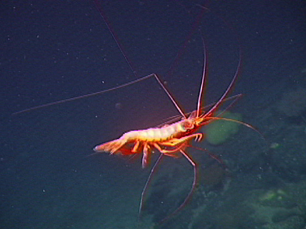 Photo by NOAA
An under water volcano

Agar, the "bacteria sample"

Team Effort
Teams consist of an electrical engineer, hull engineer, and a mechanical extension engineer. The electrical engineer wires the ROV and controls it during the competition. The hull engineer designs and builds the housing of the electrical components and the structure of the ROV. The mechanical extension engineer design and builds a claw that is capable of completing the required tasks.

Powersource that the ROV will use

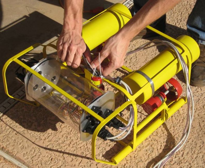
Hull of a simlpe ROV
 Allen Vanguard "Defender"
 Robotic claw

The Tau Beta Pi ROV in action at the 2008 MATE ROV Competition
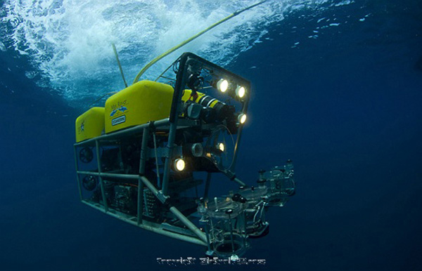
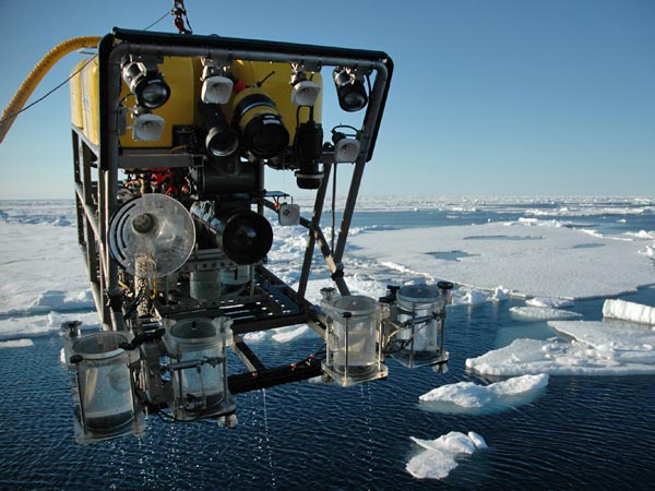
NOAA ROV
WHY IS THIS PROJECT IMPORTANT?
The MATES ROV Competition is an entry level opportunity for high school students to explore the world of robotics. Having to design and build a functioning ROV with a small group forces each student out of the common comfort zone and into the real world where students must interact with professionals in order to successfully grasp the tasks at hand. The MATES ROV competition is a chance to tryout the field of deep sea exploration, allowing students a hands on experience in a possible future career choice.
A previous competitor at the Competition

Hands on electical learning. Photo by Corbis Cooperation
 Photo by Corbis Cooperation
Cabrillo High School Aquarium ROV

Outland Tech "Outland 1000"

Sub Sea Sampling

PROJECT MOOD
To successfully design, build, and contend in the ROV project, the team needs to be focused. The competition must be conducted as a business with each member ultimately responsible for their own portions of the ROV. Regular team meetings will ensure cohesiveness and allow optimum quality of the final product.

 Man presenting at business meeting
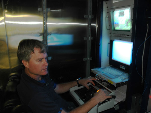
At the controls of an ROV

ROVs IN USE TODAY
Today’s problems call for the use of ROVs. The military uses ROVs to disarm bombs and mines safely without risking soldiers’ lives. ROVs are used to explore deep sea and deep space because they can go where humans cannot. Scientist use ROVs to perform different tests and take different sample. ROV versatility is endless. The most recent use of ROVs comes from deep sea repair when oil pipes ruptured. The ability to extend where humans cannot reach is an asset to knowledge.
A military ROV

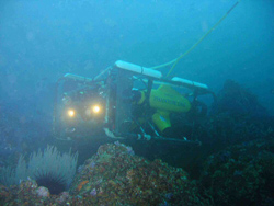
Deep Sea ROV
ROV Manipulator at work
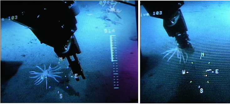
Smithsonian
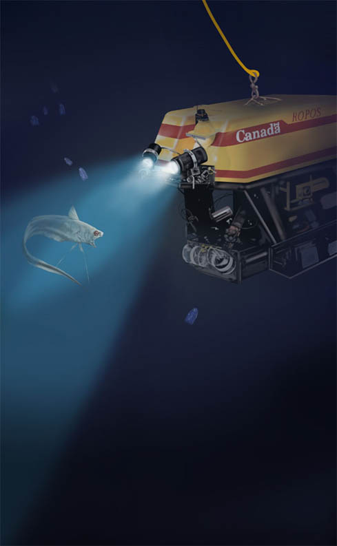
Photo by NOAA
Monday, September 13, 2010
Research/Brainstorming
Introduction
TheUniversity of Hawaii
The
The MATE Logo
Atmosphere
The Mates ROV Competition takes place in a chlorinated pool (outdoor or indoor) between 1.2 m to 4.0 meters in depth. The control station is located in a “shack” so that the controlling team member cannot see the ROV in the pool. The atmosphere is tense because each team wants to perform its best (it is a competition).
In the "shack".
 Competitors at a previous competition.
Conditions
Chlorinated pools are clear with high visibility compared to the murky water of a river, lake, or ocean. The electrical engineer must be sure that the tether and connection joint (where the ROV and tether meet). Water is highly conductible to electricity; it is imperative to contain the energy for safety reasons as well as to maintain the energy for the controlling of the ROV.
A competitor holding his tether.


The standard competition area.
Research of the End User
The electrical engineer is ultimately responsible for controlling the ROV. He is located in a shack next to the pool so he cannot see the ROV in motion. The team member in the shack controls the ROV based on what he sees on the maximum of three monitors in front of him. Other team members watch the ROV poolside during the competition. They can change the mechanical extension of the ROV during the competition if the ROV travels to them. Competitors are going to be under high amounts of stress and pressure during the competition. Humidity in the air from the pool has the possibility to be a factor because the controls are electric.
A team celebrates after their success.

Testing Procedures
Intro

Tests:
Propulsion Test: What type of propulsion works best? E Motor Bilge Pump Converted Pump
Preliminary, Exploration, Comparison
1. Wire power through 2 double pole double throw switches to a converted bilge pump and an electric motor (with propellers attached to the pump and motor).
2. Make sure each direction of switch supplies power.
3. Submerge systems in water.
4. Power both in forward direction.
5. Record which goes faster, the pump or the electric motor.
Propeller Test: What type of propeller works best?
Preliminary, Exploration, Comparison
1. Take the winning system from the Exploratory Propulsion Test and duplicate it three times
2. Outfit each different motor/pump with a different propeller
3. Wire all four of the motors/pumps in parallel
4. Submerge in water
5. Power all motors/pumps in forward direction
6. Record winner


Data Platform Test: Does the data platform work correctly when powered together?
Preliminary, Exploratory
1. Wire the camera, lighting, thermometer, and hydrophone to 12 V 25 Amp battery
2. Power all of the systems at the same time.
Tether Test: Is the tether connection water proof?
Preliminary, Exploratory
1. Cut a half inch diameter hole in the bottom of a Tupperware container
2. Put a stick through the hole and wrap the penetrating end with a wad of paper towels
3. Seal both sides with rubber cement and let dry
4. Close Tupperware container
5. Submerge in water for a minute
6. Remove container from water and remove lid
7. Record if the paper towels are wet
* if wet, try different ways of sealing

Propulsion and Data Platform Test
Final, Exploratory
1. Wire all components of the data platform and all components of the propulsion to the 12 V 25 Amp battery
2. Wire in a fuse that blows at 25 Amps
3. Power data package
4. Power on each motor until all motors and the entire data platform are operating
5. Record outcomes, can the battery support all of the systems simultaneously
Specifications and Limitations
SPECS
LIMITS
- Controller must be operable.
- Must have a forward/backwards, side/side, up and down in the water column and also opening and closing claw.
- Wiring must be out of the way of the ROV so it can perform tasks without obstruction.
- RANGER class ROVs operate at a nominal 12 volts DC, 25 amps.
- ROV must have male banana plugs to obtain power.
- Must be operable in chlorinated water.
- All power must go through an onboard fuse
LIMITS
- RANGER class ROVs operate at a nominal 12 volts DC, 25 amps.
- All power and control must pass through one fuse.
- Cannot step up power through transformers.
- Any onboard power can only power lighting and instruments.
Individual Design Brief
Design and build the electrical system that allows an operator (in the shack) to propel an ROV in the X, Y, Z axis of a chlorinated pool, operate the mechanical extension, send and retrieve temperature and hydrophone data, and power optical equipment.

http://www.treasurenet.com/f/index.php?action=dlattach%3Btopic=6544.0%3Battach=15933%3Bimage
A young explorer and his ROV controls
Group Design Brief
Design and build an ROV to compete in the MATES ROV Competition that a mission team can operate in a chlorinated pool without physically seeing the competition.
An example of the ROV Competition Arena
Introduction
My name is Matthew Gannon and I am a Senior at the Marine Academy of Science and Technology. For my Senior year, I am taking Systems Engineering II. Systems Engineering II is a course designed to teach students the Design process as well as time management and technical communication skills. Along with five other classmates, we will be building an underwater Remotely Operated Vehicle (ROV).
 Posidon: Mikael Gustafson & Chris Beebe
ROVs are important tools for human being because they have the capability to go where humans cannot. The most recent use of ROVs can be seen in the massive Gulf oil spill this summer of 2010. Hundreds of ROVs were used in an attempt to repair the broken pipes located five thousand feet below the surface. ROVs are also used for deep sea exploration. The ROV we are making will be mobile in water and have the ability to send various information to the surface.
 Posidon: Mikael Gustafson & Chris Beebe
 ROVs are important tools for human being because they have the capability to go where humans cannot. The most recent use of ROVs can be seen in the massive Gulf oil spill this summer of 2010. Hundreds of ROVs were used in an attempt to repair the broken pipes located five thousand feet below the surface. ROVs are also used for deep sea exploration. The ROV we are making will be mobile in water and have the ability to send various information to the surface.
explore.noaa.gov

Subscribe to:
Posts (Atom)